
Ever hooked up a fresh set of speakers in your car and wondered if they’ll actually sing or just sigh?
That moment of doubt is all too familiar – you’re standing in the garage, multimeter in hand, and the whole audio upgrade hangs on a single test.
Learning how to test speaker with multimeter is the fastest way to confirm polarity, resistance and whether a speaker is dead before you wire it to an amp.
In our experience at Audio Intensity, a quick resistance check saves installers hours of troubleshooting later on.
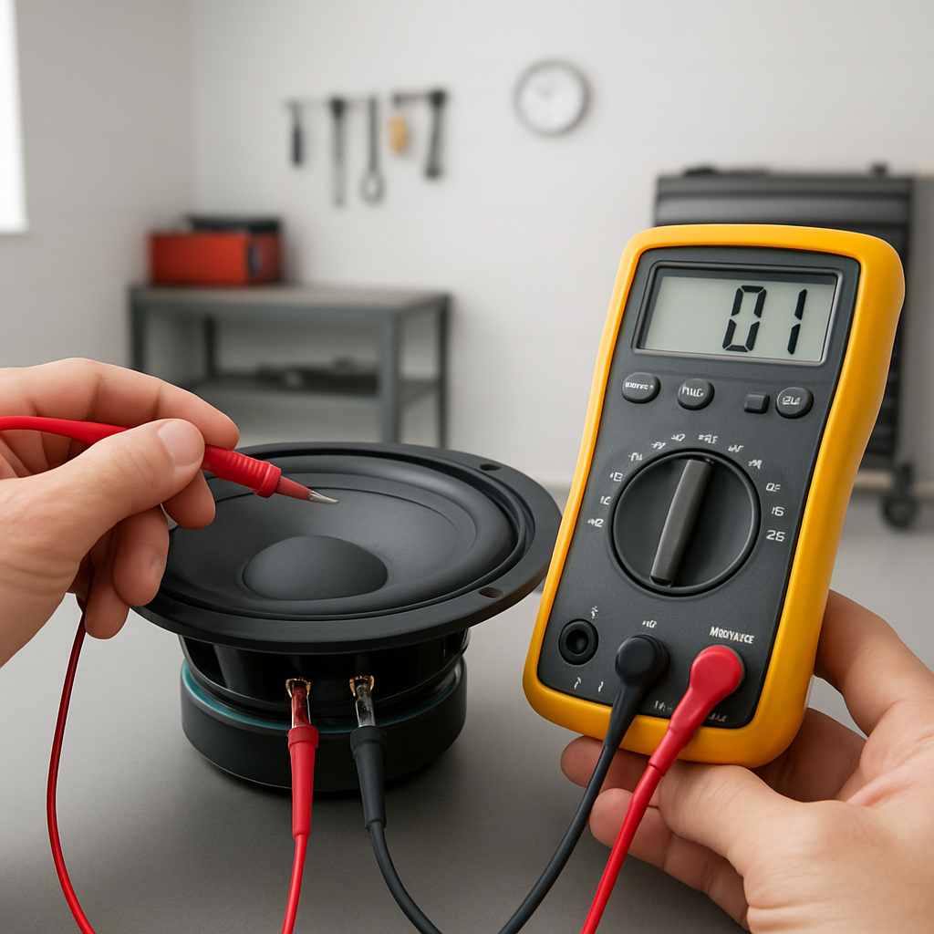
Grab a digital multimeter, set it to the ohm (Ω) range, and connect the probes to the speaker terminals. If the reading sits between 4 and 8 Ω for a typical car speaker, you’re good to go.
But what if the needle wobbles at 0 Ω or shoots off to infinity? Zero means a short – the coil is likely burnt out. Infinity means an open circuit – the speaker coil is broken.
Here’s a little tip: give the speaker a gentle tap while watching the multimeter; a stable reading that fluctuates slightly indicates the voice coil is alive.
Now, polarity matters too. Switch the probes; if the reading stays the same, the speaker’s polarity is correct. A sudden jump suggests reversed wires, which can cause phase issues once the system is powered.
Think about the last time you heard a car’s audio sound thin or hollow – often it’s a mismatched speaker wiring that a quick multimeter test would have caught.
For those custom builds, you might be using a coaxial speaker like our Audio Circle SL‑X6. The same ohm check applies, and you’ll also verify that the tweeter and mid‑range share the same impedance.
Don’t forget to disconnect the speaker from any amp or battery before testing; a live circuit can fry your meter and give false readings.
Once you’ve confirmed healthy resistance and proper polarity, you can confidently install the speaker, knowing it’ll deliver the punchy sound you expect.
So, ready to grab that multimeter and give your speakers a quick health check? Let’s dive in and make sure every note hits the right spot.
TL;DR
Quickly check any car speaker with a digital multimeter: measure resistance between 4‑8 Ω for healthy coils and flip probes to verify polarity.
If you see 0 Ω you have a short, infinity means an open circuit, so you can easily quickly fix wiring before the amp ever sees a bad speaker.
Step 1: Gather the Right Tools and Safety Precautions
Before you even think about clipping the multimeter onto a speaker, pause for a second and picture the garage floor littered with loose wires, a busted speaker, and a coffee cup you’ve tipped over. That chaotic moment is exactly why we start with the right tools and a solid safety plan – it saves you from a handful of headaches later.
First up, you’ll need a digital multimeter that can read ohms. If you’re still using an analog meter, consider upgrading; the digital readout makes it far easier to spot that dreaded 0 Ω short or an infinite‑ohm open circuit. Grab a set of insulated probe leads – the kind with a rubber grip – so you don’t accidentally nick yourself or the speaker’s terminals.
Safety Gear You Can’t Skip
Even though you’re only dealing with low‑voltage stuff, a few safety habits go a long way. Slip on a pair of safety glasses to protect your eyes from any stray solder splatter or wire insulation bits. If you’ve got a shop vacuum nearby, keep it running to pull away dust; a dusty environment can cause false readings.
Make sure the vehicle’s battery is disconnected, or at the very least, the negative terminal is clipped off. A live circuit can fry your multimeter’s fuse and give you a misleading reading. And while you’re at it, label each speaker wire with a durable sticker so you don’t lose track of polarity – custom printed labels from JiffyPrintOnline are perfect for this job.
Next, clear a workspace on the passenger side floor. Lay down a non‑conductive mat – a rubber garage mat works great – and keep your tools within arm’s reach. This little setup reduces the chance of knocking a probe into the car’s chassis and short‑circuiting something.
Gather the Essentials
Here’s a quick checklist you can print out (or jot on a sticky note):
- Digital multimeter set to the Ω (ohms) range
- Insulated probe leads
- Safety glasses and gloves
- Battery disconnect tool or wrench
- Wire strippers and a small screwdriver
- Label maker or custom stickers for wire identification
When you’ve got everything laid out, give yourself a moment to double‑check the multimeter’s battery. A weak battery can cause the display to flicker, making it hard to trust the numbers you see.
Now, let’s talk about grounding. Even with the battery disconnected, the car’s chassis can act as a ground path. Use a spare piece of wire to create a temporary ground reference point on the vehicle’s metal frame; this ensures your multimeter readings are stable and not floating.
And if you’re the type who loves a little extra polish, consider adding a dash of LED ambience to your install – LED Artistry offers professional lighting solutions that pair nicely with a clean, well‑tested audio system.
Once your toolbox is set, you’re ready to move on to the actual testing. But before we dive into the ohm‑checking steps, here’s a quick visual guide that walks you through the probe placement.
Take a moment to watch the video – it shows the exact hand‑positioning you’ll need, and you’ll see how a steady hand makes all the difference when you’re measuring a speaker’s coil resistance.
When you’re comfortable with the visual, go back to your checklist and verify you’ve got the safety glasses on, the battery disconnected, and the custom labels ready. If anything feels off, pause and fix it – rushing this part is the fastest way to end up with a fried multimeter or a mislabeled wire.
Finally, for a broader perspective on tool gathering, check out our Easy Steps to Mastering Car Audio for Beginners. That guide walks you through everything from screwdrivers to wire strippers, so you won’t miss a single piece of essential gear.
With your tools assembled and safety measures in place, you’re now primed to move onto the next step: actually measuring speaker impedance and confirming polarity. Trust the process, stay methodical, and you’ll avoid the common pitfalls that trip up even seasoned installers.
Step 2: Identify Speaker Terminals and Prepare the Multimeter
Now that your battery is safely disconnected and your tool kit is within reach, the next thing you need to do is actually locate the speaker terminals you’re about to test. It sounds simple, but in a cramped door panel or behind a dashboard trim piece those little metal contacts can hide like a needle in a haystack.
First, pull off any trim that’s covering the speaker. Most factory doors use a few plastic clips; a flat‑head screwdriver or a trim‑removal tool will pop them without cracking the panel. As you peel back the cover, you’ll see two wires – usually a red (+) and a black (–) – leading into a pair of metal terminals stamped “+” and “–”. If the wires are already stripped, you’ll see the copper conductors exposed. If they’re still covered with factory‑type crimp sleeves, gently cut the sleeve back with a wire‑stripper so the multimeter probes can make solid contact.
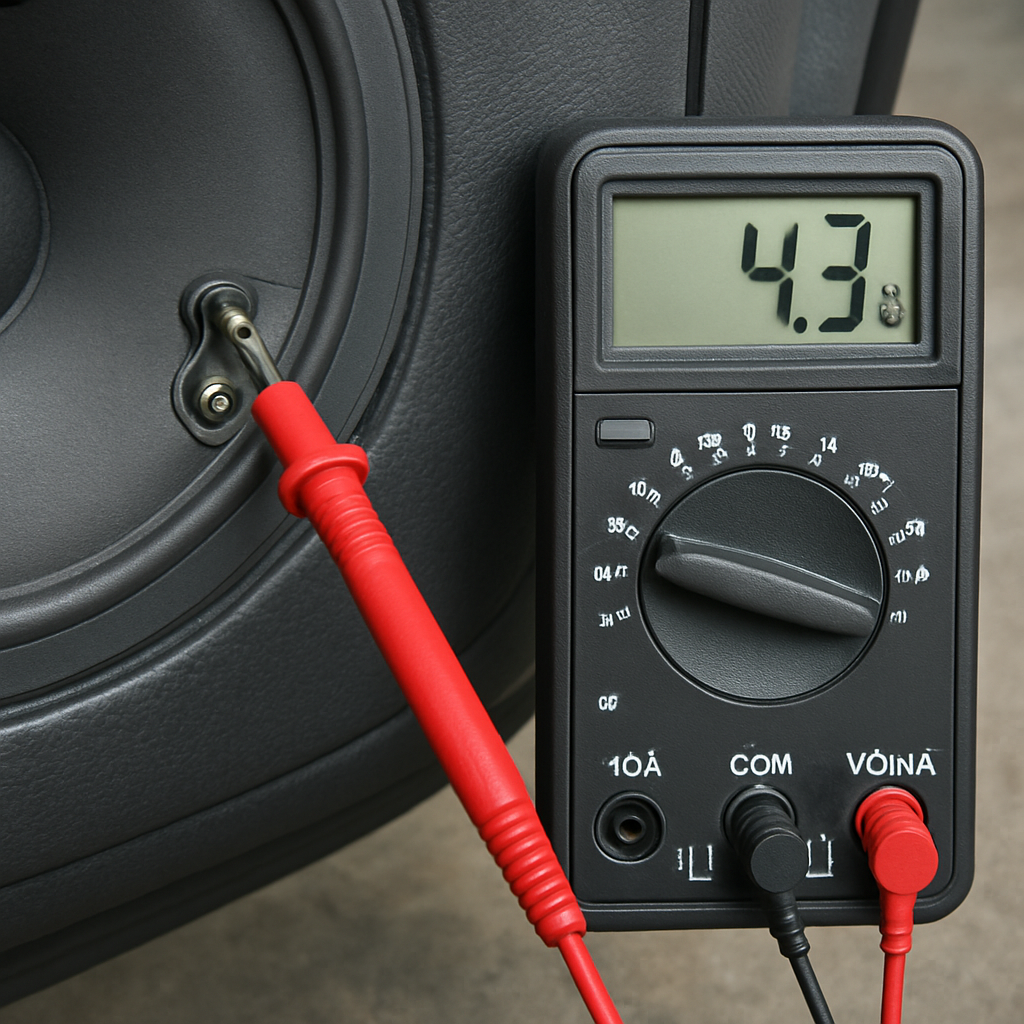
Now grab your digital multimeter and set it to the resistance (Ω) range. Most modern meters default to the 200 Ω setting, which is perfect for the 4‑8 Ω range you’ll see on typical car speakers. If you’re working with a subwoofer that’s rated at 2 Ω or 4 Ω, you can still stay on the 200 Ω scale – the reading will just be a small number, but it’ll be accurate.
Before you touch the probes to the speaker, double‑check that the multimeter’s leads are in good condition. A frayed tip can give you a false low‑ohm reading that looks like a short circuit. Give each lead a quick visual inspection, and if you see any exposed wire, trim it back with the cutter on the probe’s end. A clean, snug connection is the difference between a trustworthy reading and a mystery you’ll chase later.
Here’s a quick three‑step checklist to get the terminals ready for testing:
Quick three‑step checklist
- Locate the two terminals, note the polarity markings, and make sure they’re free of corrosion.
- Strip back any factory crimp sleeves just enough to expose clean copper – no more than a half‑inch.
- Connect the multimeter leads to the corresponding + and – terminals; a firm clip prevents slipping while you read the value.
When you finally place the probes, you’ll usually see a stable reading between 4 Ω and 8 Ω for most mids and tweeters. If the meter flickers wildly or reads zero, you’ve either got a shorted coil or a loose connection. A common scenario I’ve seen in busy install shops is a speaker that’s been re‑wired with aftermarket wire, and the installer forgets to remove the factory crimp sleeve. The meter will jump to “OL” (open line) because the sleeve insulates the probe – a quick slice of the sleeve fixes it instantly.
If you’re dealing with a coaxial unit like our Audio Circle SL‑X6, you have two sets of terminals: one for the woofer cone and one for the tweeter dome. Test each pair separately – you’ll get roughly the same ohm value for both, but a mismatch (say 4 Ω on the woofer and 6 Ω on the tweeter) can hint at a wiring error or a damaged dome. In practice, I always label the tweeter leads with a tiny “T” sticker so I never confuse them during the final install.
Step 3: Measure Speaker Impedance (Resistance)
Alright, you’ve got the meter set, the battery is off, and the terminals are exposed – now it’s time to actually read the impedance. This is the moment that tells you whether the speaker will play nicely with the amp or scream in protest.
What you should see
For most mids, tweeters, and 6×9 doors you’ll land somewhere between 4 Ω and 8 Ω. A 2‑Ω sub will sit right around 2 Ω, and a 1‑Ω high‑power unit will read close to 1 Ω. Anything dramatically lower than the spec – like 0 Ω – means the coil is shorted. Anything way higher – “OL” or infinity – points to an open circuit or a broken wire.
And if you see a wobble between those numbers, that’s usually a loose connection or a stray bit of insulation still hanging on the lead.
Step‑by‑step checklist
- Grab the two probes and place one on the + terminal, the other on the – terminal.
- Read the stable value. Write it down next to the speaker model.
- If you have a coaxial unit, repeat the process for the tweeter pair.
- Compare each reading to the manufacturer’s spec sheet.
- Mark any out‑of‑range speaker with a bright sticker so you don’t forget to re‑wire or replace it.
Simple, right? But a couple of quirks can trip even seasoned installers.
Real‑world scenarios
Scenario 1: A friend of mine was swapping a set of 4‑Ω door speakers for a pair of 6‑Ω aftermarket units. He measured 5 Ω on the left and 8 Ω on the right. The higher reading turned out to be a thin‑film crimp sleeve that hadn’t been fully stripped. A quick slice of the sleeve brought the reading down to the expected 6 Ω and the system sounded balanced.
Scenario 2: In a busy shop we once got a 2‑Ω sub that read 0 Ω on the meter. The amp was already wired in, and the sub was making a faint click when powered. The short was caused by a nicked wire that touched the chassis ground. Isolating the wire and re‑soldering fixed the short, and the sub roared back to life.
These little stories illustrate why a clean, confident reading matters – it saves you from hunting down a phantom problem later.
Pro tip from the floor
While the probes are on the terminals, give the cone a gentle tap with a plastic screwdriver. If the impedance wiggles just a tad and settles, the voice coil is alive. A dead coil will stay flat, and a short will stay at zero.
Also, always test in a stable temperature. Cold speakers can read a few ohms higher because the copper resistance rises a bit. If you’re in a chilly garage, let the speaker warm up for a minute before taking the final reading.
What to do with the data
If the measured impedance matches the spec, you’re good to connect the speaker to the amp. If it’s lower, consider adding a series resistor or swapping the speaker for a higher‑impedance model – otherwise you risk over‑loading the amp.
When it’s higher, double‑check your wiring: a stray wire to ground or a partially stripped lead can add extra resistance. Fix the wiring and re‑measure; you should be back in the 4‑8 Ω sweet spot.
And remember, the goal isn’t just to get a number – it’s to confirm that the speaker will cooperate with the rest of the system. A healthy impedance reading means you can move on to the next step with confidence.
Step 4: Interpret Results and Compare to Speaker Specs
Now that you’ve got a stable resistance reading, the real question is what that number means for your amp and your car’s sound system. It’s one thing to see a number on the meter; it’s another to know whether that number will let your speakers sing or scream.
First, pull up the speaker’s nominal impedance rating – usually printed on the back of the cone or in the product’s spec sheet. That rating is the target you’ll compare your multimeter reading against. Most factory door speakers sit at 4 Ω, mids often at 6 Ω, and sub‑woofers can be 2 Ω or 4 Ω.
Here’s the rule of thumb most installers swear by: the measured resistance should be about 15 % lower than the nominal impedance because the multimeter reads DC resistance, not the true AC impedance the amp sees. WikiHow explains the 15 % rule, and you’ll find it matches what we see in the shop day‑in, day‑out.
So, if you’re testing a 4 Ω speaker and your meter shows 3.4 Ω, you’re right on the money. If it reads 2.8 Ω, that could indicate a short or a partially damaged coil. If it jumps to 5.5 Ω, you’re probably looking at extra series resistance from a bad solder joint or a stray wire touching chassis ground.
Low‑impedance red flag
A reading that’s noticeably lower than the 15 % window usually means the coil is shorted or there’s an unintended path to ground. Imagine you’re installing a 2 Ω sub in a compact hatchback, and the meter flashes 0.6 Ω. That’s a classic short – maybe the speaker wire was nicked against a metal bolt during the door‑panel removal.
What to do? Disconnect the speaker, inspect the leads for nicks or exposed strands, and re‑solder or replace the wire. If the coil itself is shorted, the safest move is to swap the sub for a fresh unit – a short will force the amp to deliver far more current than it’s designed for, potentially frying the amp.
High‑impedance warning
On the flip side, a reading that’s higher than the spec (or shows “OL” on the meter) points to an open circuit. A common culprit is a partially stripped wire that still has a bit of insulation between the copper and the probe, or a loose terminal that isn’t making solid contact.
Real‑world scenario: an installer was fitting a set of 6 Ω coaxial speakers in a sedan and measured 7.2 Ω on the tweeter side. A quick visual check revealed a thin factory‑crimp sleeve that hadn’t been fully cut back. Trimming the sleeve brought the reading down to 6.1 Ω, and the soundstage instantly widened.
When the numbers sit in the sweet spot
If your measurement falls within the 15 % tolerance band, you can breathe easy. That means the voice coil is healthy, the wiring is clean, and the speaker will draw the right amount of current from the amp. At this point you can move on to power‑on testing, confident the system won’t stress the amp or produce distortion.
- Write down the measured value next to the speaker model.
- Cross‑reference with the spec sheet’s nominal impedance.
- Apply the 15 % tolerance rule.
- If out of range, troubleshoot: check for shorts, inspect wire insulation, verify proper stripping.
- Retest after any fix before reconnecting the amp.
Seeing the numbers line up is satisfying, but it also tells you whether you need to add a series resistor, swap the speaker, or simply tighten a connection. Those small adjustments can mean the difference between a clean, punchy bass line and a cracked‑speaker mess.
After the video, take a moment to double‑check your notes. A quick glance at the table below can help you decide what action to take based on the range your reading falls into.
| Measured Ω | Nominal Ω (Spec) | What to Do |
|---|---|---|
| 0 Ω – 0.9 × nominal | 2 Ω, 4 Ω, 6 Ω, 8 Ω | Inspect for shorts, re‑strip wires, replace speaker if coil is damaged. |
| 0.85 × – 1.15 × nominal | 2 Ω, 4 Ω, 6 Ω, 8 Ω | All good – proceed to amp connection. |
| >1.15 × nominal or “OL” | 2 Ω, 4 Ω, 6 Ω, 8 Ω | Check for stray insulation, loose terminals, or broken wire; re‑strip and retest. |
Use this quick reference whenever you finish a measurement. It keeps the decision‑making process fast, especially when you’re juggling multiple doors or a custom sub‑woofer install.
Step 5: Test Speaker Continuity and Detect Shorts
Now that you’ve nailed the resistance numbers, it’s time to make sure the speaker isn’t secretly talking to the chassis. Continuity testing is the safety net that catches a hidden short before you crank the amp up to eleven.
Why continuity matters
A shorted voice coil will read near 0 Ω and can drag the amplifier into thermal shutdown the moment power hits the speaker. Even a tiny stray strand of wire touching metal can create that dreaded zero‑ohm path, and the result is a dead speaker, a fried amp, or a puff of smoke that no one wants in a garage.
For car‑audio enthusiasts and professional installers, catching the short early saves time, money, and reputation. In our experience, the majority of “no sound” complaints in custom builds come from an unnoticed short rather than a bad speaker.
How to run a continuity check with a multimeter
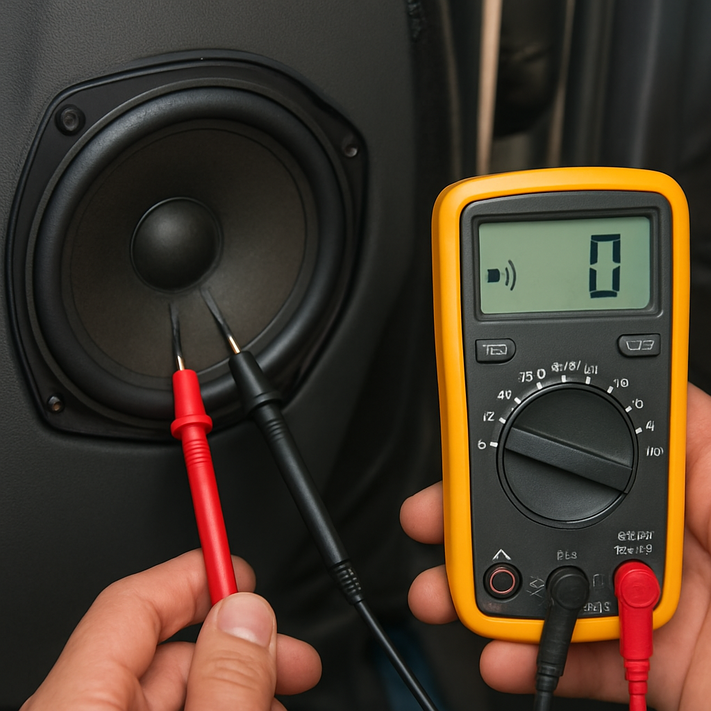
1. Switch your digital multimeter to the continuity or diode‑test mode – most meters show a beep when the circuit is closed.
2. Keep the battery still disconnected and the speaker isolated from any wiring harness.
3. Touch the probe tips together first; you should hear a clear tone. That confirms the meter is working.
4. Place one probe on the positive terminal and the other on the negative terminal. If you hear a beep, the coil is continuous and the reading should sit around the expected resistance range (usually 0.8‑1.0 × the spec). No beep means an open circuit – the coil is broken.
5. Next, put one probe on each terminal and the second probe on any nearby chassis ground point (the metal body of the door or a bolt). A beep here signals a short to ground.
When you hear a tone on the ground test, pull the speaker out and inspect the leads. Look for nicked insulation, stray strands, or a loose crimp that might be touching the metal frame. Trim the offending wire, re‑strip, and test again.
Spotting a short in real‑world scenarios
Imagine you’re installing a pair of 4 Ω Audio Circle SL‑X6 coaxials behind a door panel. After wiring, the multimeter reads 0.2 Ω between the terminals – a classic short. A quick visual check reveals the speaker’s mounting bracket is rubbing against a metal screw, shaving the wire insulation. A little bit of heat‑shrink tubing and the short disappears.
Another common case: you’ve routed a new speaker wire through a factory‑mounted harness and the wire’s shield has peeled back, making contact with the car’s chassis ground. The continuity test will beep on the ground check even though the terminal‑to‑terminal reading looks fine. That’s why you always do both checks.
Quick continuity checklist
- Set meter to continuity mode and verify the beep with probes together.
- Test terminal‑to‑terminal – expect a beep and a resistance within 15 % of spec.
- Test each terminal against chassis ground – no beep, no short.
- If a beep appears on the ground test, locate and isolate the offending wire.
- Re‑measure after any repair; only proceed when the ground test stays silent.
Once the continuity test is clean, you can move on to hooking the speaker up to the amplifier with confidence. No hidden shorts, no surprise amp shutdowns – just a smooth rollout of that new sound you’ve been dreaming about.
If you want a visual walk‑through of the continuity check, watch a quick continuity demo – the video walks you through the same steps we just covered.
Step 6: Advanced Checks – Sensitivity and Power Handling
Now that the continuity and impedance are clean, it’s time to dig a little deeper and make sure the speaker will actually sing the way you expect. This is where “how to test speaker with multimeter” meets a bit of audio theory, and a few extra tools can save you from a nasty surprise when you crank the amp.
Ever wonder why two speakers that read the same ohms can sound totally different? The secret often lies in sensitivity and how much power the driver can safely handle.
Measuring Sensitivity with a Multimeter and a Signal Source
Sensitivity is the sound pressure level (SPL) a speaker produces when fed 1 W of power at 1 m distance. While a proper SPL meter is the gold standard, you can get a reasonable ballpark using a multimeter, a 1 W resistor, and a steady 1 kHz sinewave from a signal generator or your head‑unit.
Here’s a quick step‑by‑step:
- Set your multimeter to AC voltage (200 mV range works for most 1 W tests).
- Connect a 4 Ω power resistor in series with the speaker – this acts as a dummy load to keep the amp stable.
- Play a 1 kHz tone at full volume from the source. Measure the voltage across the speaker terminals.
- Use the formula P = V² / R to calculate the wattage actually reaching the speaker (R is the speaker’s rated impedance). Aim for ~1 W.
- If you hit roughly 1 W and the meter reads about 2.8 V on a 4 Ω speaker, the speaker’s sensitivity is around 88 dB. Adjust the source level until you hit 1 W and note the voltage – this gives you a practical sensitivity estimate.
Why does this matter? A higher‑sensitivity driver (90 dB + ) will hit louder levels with less amp juice, while a low‑sensitivity unit needs more power to keep the music punchy. Knowing this helps you match the speaker to the amplifier’s output without over‑driving.
Checking Power Handling without Burning Anything
Power handling is the amount of continuous RMS power a speaker can tolerate before the voice coil overheats. The safe route is to verify the manufacturer’s RMS rating, but you can also use the multimeter to spot early signs of overload.
Try this:
- Disconnect the speaker from the car’s main harness and attach it to a bench‑power amp that lets you set a precise RMS output.
- Start at 25 % of the rated RMS power. Use the multimeter in DC voltage mode to monitor the amp’s supply voltage – a sudden dip can indicate the speaker is pulling too much current.
- Listen for distortion or a “grinding” sound. If you hear it before reaching the spec, the speaker’s thermal limit is lower than advertised.
- After a few minutes at each power step, pause and feel the cone with a gloved hand. A warm but not hot cone is normal; any scorching smell means you’ve crossed the safe line.
Remember, the multimeter isn’t measuring acoustic power directly, but it tells you whether the electrical load is staying stable. A steady voltage reading means the coil isn’t drawing excessive current, which usually translates to safe thermal conditions.
Practical Tips for Installers
• Always double‑check the speaker’s nominal impedance before you set the test power. Feeding 4 W into a 2 Ω sub will double the current and can fry the coil in seconds.
• Use a heat‑shrink sleeve on any exposed leads after you’ve verified the tests – it prevents accidental shorts that could skew your measurements later.
• If you’re swapping a low‑sensitivity door speaker for a high‑output aftermarket model, consider adding a small series resistor (0.5 Ω) to protect the amp during the first few weeks of break‑in.
And here’s a little habit that saves a lot of headache: after each sensitivity or power test, jot down the voltage, calculated wattage, and any audible observations in a quick spreadsheet. Over time you’ll build a reference library that tells you exactly what “good” looks like for each speaker you install.
So, what’s the next step? Once you’ve confirmed that the speaker’s sensitivity aligns with your listening goals and that the power handling checks stay within safe limits, you can finally wire the unit to the amp with confidence. No surprises, no blown tweeters, just a clean, powerful soundtrack for every drive.
Conclusion
We've walked through every step of how to test speaker with multimeter, from safety prep to reading impedance, continuity and even a quick sensitivity check. By now you should feel comfortable grabbing the meter, probing the terminals, and interpreting those numbers without second‑guessing yourself.
So, what’s the next move? Grab a quick notebook, jot down each speaker’s measured Ω, compare it to the spec, and flag anything outside the 15 % tolerance. A simple spreadsheet becomes your cheat sheet the next time you swap a door speaker or install a new sub.
Remember, a clean reading means the voice coil is healthy, the wiring is solid, and your amp will stay cool – no surprise blow‑outs in the middle of a road trip. If you do spot a short or an odd high reading, a bit of heat‑shrink and a re‑strip usually fixes it before you ever power up the system.
In our experience, installers who make the quick “write‑it‑down” habit cut troubleshooting time by half. It also builds a reference library that pays off when you move from one vehicle to the next.
Finally, take a moment to double‑check your battery disconnect and safety gear before you reconnect the amp. A few seconds of caution saves hours of frustration.
Happy testing, and enjoy that clean, punchy sound you’ve earned.
FAQ
What’s the first thing I should check before I start how to test speaker with multimeter?
Before you even touch the probes, make sure the vehicle’s battery is disconnected and the speaker is isolated from any power source. A quick visual inspection for loose wires, corrosion, or stray strands saves you from reading phantom shorts. Grab a notebook, jot down the speaker model, and have your multimeter set to the lowest resistance range – that way you won’t be guessing.
Can I use the resistance setting on any digital multimeter for speaker testing?
Yes, any decent digital multimeter with an Ω (ohm) setting will work, but you’ll get the most reliable numbers on a meter that displays two decimal places. Set it to the 200 Ω range – that covers the typical 4 Ω to 8 Ω car speakers. If your meter has an auto‑range feature, let it settle before you probe; a stable readout means the meter’s internal calibration is happy.
How do I interpret a reading that’s lower than the speaker’s nominal impedance?
A lower‑than‑spec reading usually signals a shorted coil or a stray wire touching the chassis. For example, a 4 Ω speaker showing 2.5 Ω is outside the 15 % tolerance we recommend. Double‑check the leads for nicked insulation, and if the short persists, the voice coil itself may be damaged – in that case swapping the unit is the safest route.
What does an “OL” or infinite reading tell me during testing?
“OL” (open line) means the multimeter sees essentially infinite resistance – the circuit is broken. Common culprits are a fully stripped wire that never makes contact, a factory crimp sleeve that still covers the copper, or a loose terminal. Strip just enough copper to expose the conductor, retest, and you should see a normal 4‑8 Ω value appear.
Is it safe to test speakers while they’re still wired to the car’s harness?
Never. Even with the ignition off, residual voltage can linger in the harness, especially in modern cars with standby power. Keep the negative battery terminal disconnected and verify there’s zero volts at the speaker terminals with the multimeter on DC voltage mode. Once you have a clean, dead circuit, you can safely probe the impedance without risking a short or a fried meter.
How often should I record my measurements and why?
Every time you pull a speaker out or swap a component, jot down the measured Ω next to the model number. Over time you’ll build a personal reference sheet that instantly tells you when a reading is out of range. Installers who keep a spreadsheet cut troubleshooting time in half because they spot anomalies before the amp even sees a signal.
What common mistakes cause false readings when using a multimeter on speakers?
First, using frayed or dirty probe tips can add extra resistance, making a healthy speaker look like a short. Second, leaving the battery connected introduces stray voltage that skews the reading. Third, accidentally measuring across a grounding point instead of the two speaker terminals gives you an “OL” or zero reading. Clean the probes, double‑check your connection points, and always isolate the speaker before you start.


