
Ever cracked open the hood and stared at that sleek amplifier, wondering if it’s actually alive?
We’ve all been there – the silence after you hit the radio, the suspicion that something inside the box is off, and the fear of spending a fortune on a replacement that might just be a simple wiring glitch.
That’s why learning how to test car amp with multimeter is a game‑changer for any car‑audio enthusiast, installer, or hobbyist who likes to keep the garage humming without the guesswork.
In our workshop at Audio Intensity, we’ve seen a dozen different “it won’t turn on” scenarios, and more often than off the culprit is something you can spot in five minutes with a digital multimeter.
So, what exactly are we looking for? First, you want to confirm the power rails are delivering the right voltage, then you’ll check the speaker outputs for continuity, and finally you’ll verify the ground isn’t floating.
Don’t worry if you’ve never held a multimeter before – the tool is pretty forgiving. Set it to the DC voltage range for the battery check, switch to resistance (Ω) for continuity, and you’ll hear a beep if the path is solid.
Imagine you’re pulling a Friday‑night jam in a ute, and the bass just drops out. A quick glance at the amp’s voltage with the multimeter can tell you whether the fuse blew, the wiring pinched, or the amp itself is on its last legs.
And here’s a little tip we’ve picked up: always double‑check the polarity before you clip the probes, because a reversed lead can give you a misleading zero reading and waste precious time.
By the end of this guide, you’ll be able to walk into any vehicle, snap the multimeter onto the amp, and walk out with a clear diagnosis – no guesswork, no expensive “call‑out” fees.
Ready to get your hands on the meter and bring that amp back to life? Let’s dive in and break down each step, one practical test at a time.
TL;DR
If your car amp suddenly goes silent, a quick glance with a multimeter can reveal whether the power rail, speaker output, or ground is at fault. Follow our step‑by‑step guide on how to test car amp with multimeter and you’ll pinpoint the issue in minutes, saving time and costly repairs.
Step 1: Prepare Tools and Safety Precautions
Before you even think about clipping the multimeter onto the amp, you’ve got to make sure you’ve got the right kit in hand and that you’re working in a safe environment. Trust me, a little prep saves you from a lot of guesswork – and a few bruised fingers.
Grab a digital multimeter that can read DC voltage and continuity, a set of insulated probe leads, a small screwdriver set (flat‑head and Phillips), and a pair of needle‑nose pliers. A good quality fuse puller is also handy because you’ll likely be checking the power fuse first. If you’re working in a tight engine bay, a flashlight with a magnetic base or a headlamp frees up both hands.
Safety first: disconnect the car’s battery – at least the negative terminal – before you start poking around. That cuts any stray voltage that could surprise you. Wear safety glasses, keep a fire‑extinguishing blanket nearby, and make sure the vehicle is in park with the parking brake engaged. If you’re on a lift, double‑check that it’s locked.
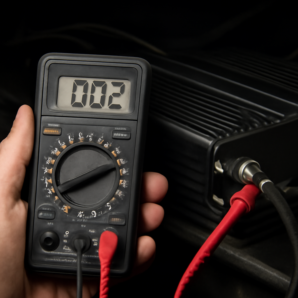
And here’s a quick visual reminder of what a properly set‑up workspace looks like:
Once the battery’s off, flip your multimeter to the DC voltage range that matches your vehicle’s system – usually 12‑20 V for most cars. For continuity checks, turn the dial to the Ω (ohms) setting and listen for that reassuring beep. Remember, polarity matters: the red probe goes to the positive side, black to ground. A reversed lead will read zero and send you down a rabbit hole.
If you ever need a quick reference while you’re at the bench, our Amplifier Testing Guide Without a Car walks you through the same steps without having to lift the amp out of the vehicle.
While you’re gathering tools, it doesn’t hurt to skim a broader safety checklist. According to A Practical Guide to Help Desk Outsourcing for SMBs, even tech‑heavy environments benefit from a clear “turn‑off‑power‑first” rule – the same principle applies under the hood.
And if you’re a DIY‑enthusiast who also runs a small business website, you might appreciate the design perspective from Website design packages pricing guide for Australian SMBs. It’s a reminder that good prep, whether for audio or web projects, always starts with a solid plan.
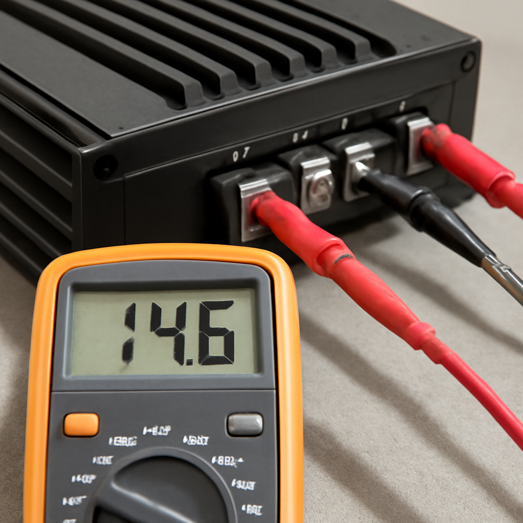
Now you’re ready to move on to the actual voltage test. With the battery re‑connected, clip the red probe to the amp’s +12 V rail and the black probe to a solid chassis ground. You should see somewhere between 13.5 V and 14.8 V when the engine is running. Anything lower could point to a blown fuse, a weak battery, or a faulty power wire – all of which you can troubleshoot before you even touch the signal side.
Take a moment to jot down the readings, snap a quick photo for reference, and keep that notebook handy for the next steps. When you’ve got the tools, safety gear, and baseline numbers sorted, the rest of the guide will feel like a walk in the park.
Step 2: Locate and Identify the Amp Terminals
Now that you've got your meter ready and the battery disconnected, it's time to hunt down the three pins that actually matter – B+, GND and REM. If you stare at the amp bay and feel like you're searching for a needle in a haystack, you're not alone. Most modern amps hide those terminals behind a little plastic cover or a snug metal bracket.
Why those three wires?
Think of B+ as the lifeline, GND as the safety net, and REM as the on‑off switch that tells the amp when the head‑unit wants it to wake up. Without a solid connection at any of those points, the amp either stays dead, snarls with noise, or goes into protection mode.
Step‑by‑step terminal hunt
1. Visually scan the back of the amp. You'll usually see a row of solder tabs or screw terminals. Look for colour cues – red is almost always B+, black or brown is ground, and a thin blue or green wire is the remote turn‑on.
2. Consult the wiring diagram. If the amp came with a schematic (most Audio Intensity units do), follow the line that says “B+” straight to the battery feed. The diagram will also tell you where the ground strap bolts to the chassis.
3. Use your multimeter’s continuity test. With the amp unplugged, set the meter to the buzzer mode. Touch one probe to the suspected ground tab and the other to a clean metal spot on the car’s chassis. A steady beep means you've found a good ground.
4. Label as you go. Grab a piece of masking tape and a Sharpie. Write “B+”, “GND”, or “REM” on each terminal. This tiny habit saves you from mixing up leads later, especially when you're juggling multiple amps in a high‑power install.
5. Double‑check polarity. Clip the red probe to the red (or marked “+”) terminal and the black probe to the ground. Your meter should read zero resistance between the two if they're truly the same point—any reading above a few ohms signals a loose wire or corrosion.
Does that sound like a lot? It's actually the part where most DIYers trip up, because a corroded ground can masquerade as a dead amp. A quick scrape with sandpaper and a fresh ring terminal often revives a unit that looked toast.
Common roadblocks
Sometimes the amp is mounted in a tight corner and the terminals are hidden behind a heat‑sink. In those cases, gently pry the heat‑sink off – it's usually held by a couple of screws. Don't force it; you don't want to crack the casing.
Other times you'll encounter a “factory‑wired” amp that already has a fused B+ lead and a ground strap clipped to the vehicle frame. If the strap looks rusty, give it a quick clean with a wire brush before you test continuity.
Need a deeper dive on why a solid ground matters? Tools Advisers explains the impact of ground resistance on amp performance. Their guide walks through the same continuity check we just described, plus a few extra tips for high‑gain setups.
Once you’ve marked those three pins, you’re set to move on to the voltage verification in the next step. Grab your meter, place the red lead on B+ and the black on GND, and let’s see if the amp is actually seeing battery power.
Step 3: Set the Multimeter to the Correct Measurement Mode
Now that you’ve got the amp’s pins marked, it’s time to tell your multimeter what you actually want to measure. If you’re still on “auto‑range” and the needle is dancing, you’ll end up with a confusing readout and wasted time.
Pick the right dial position
Most digital meters have a rotary knob with sections for DC voltage (V‑), AC voltage (V~), resistance (Ω) and a buzzer for continuity. For a car amp you’ll mainly be toggling between DC voltage and resistance.
Set the dial to the 20 V DC range when you’re checking the B+ rail or the remote turn‑on voltage. Anything above 20 V would be unusual in a 12‑V system, so this range gives you a clear, stable number without the meter trying to guess.
If the dial is on the 200 V AC setting, you’ll see “‑‑‑” or a wildly fluctuating readout – that’s because the meter is looking for alternating current, not the steady DC the amp expects.
When to use resistance (Ω) or continuity
Switching to the Ω setting lets you verify that the ground strap really is a solid connection. You’ll hear a beep if you’re on continuity mode, or you’ll see a low‑ohm number if you stay on resistance.
Understanding the difference between continuity and resistance can save you a lot of guesswork. As explained in a handy guide, continuity is essentially a very low resistance measurement that tells you whether electricity can flow freely — perfect for checking ground straps and speaker wires learn more about continuity vs resistance.
Step‑by‑step dial dance
1. Turn the knob to the “V‑” section. Look for the “20 V” or “20 V DC” label. That’s the setting you’ll use for B+ and REM.
2. Clip the black lead into the COM port and the red lead into the VΩmA port – you already did this in Step 1, but double‑check the plugs are snug.
3. Place the red probe on the B+ terminal and the black probe on GND. The meter should read somewhere between 12 V (engine off) and 14.5 V (engine running). If it’s lower than 11 V, you probably have a blown fuse or a loose battery cable.
4. Flip the dial to the Ω setting. Now test the ground strap by touching one probe to the GND tab and the other to a clean metal spot on the chassis. Anything under 0.5 Ω is solid; higher numbers mean corrosion or a bad connection.
5. Finally, set the dial back to DC voltage and give the REM wire a quick check. You should see a small voltage (usually under 1 V) when the key is in the “ACC” position – that tells the amp the head‑unit is asking it to turn on.
Quick tips to avoid common pitfalls
Don’t forget to zero‑out the meter if you’re using the resistance mode on an older analog model – a stray reading can make you think the ground is bad when it isn’t.
Keep the probes clean. A bit of oil or rust on the tip can add a fraction of an ohm, enough to throw off a tight tolerance check.
If you get a “OL” or “1 L” readout on the resistance scale, that means open circuit – the meter can’t find a path. Re‑seat the ground strap or check the bolt for stripped threads.
Lastly, remember that the multimeter itself needs power. A low battery in the meter can cause erratic voltage readings. Swap the internal button cell if the display looks dim or the numbers jump around.
With the dial set correctly, you’ve turned a vague guess into a precise measurement. The next step will be to actually compare those numbers against what the amp should see, and that’s where the diagnosis becomes crystal clear.
Step 4: Read and Interpret Voltage/Resistance Values
Alright, you’ve got the multimeter on B+, GND, and REM. The needle (or digital read‑out) is finally speaking – now it’s time to actually listen to what it’s saying.
Do you remember that tiny voltage you saw when the key was in ACC? That sub‑volt number is the amp’s “wake‑up” cue. If it’s missing, the amp never even knows it should turn on.
What the numbers mean
When you measure the B+ pin you’re looking for somewhere between 12 V (engine off) and 14.5 V (engine running). Anything below 11 V usually points to a weak battery, a blown fuse, or a bad feed wire.
The REM pin should sit under 1 V when the key is in ACC and jump to a few volts when the head‑unit tells the amp to fire. If you see a solid 12 V on REM, you’ve probably mixed up the leads or the vehicle’s remote‑turn‑on line is permanently tied to power.
Resistance checks are even more straightforward: a good ground strap reads under 0.5 Ω, often closer to 0.1 Ω. Anything higher means corrosion, a loose bolt, or a frayed strap.
Quick sanity check
Grab a piece of paper and jot down three numbers: B+ voltage, REM voltage (ACC), and ground resistance. Compare them to the table below – it’s your instant go/no‑go board.
| Parameter | Ideal Range | Red Flag |
|---|---|---|
| B+ Voltage (engine off) | 12.0 V ± 0.5 V | <11 V or >13 V |
| REM Voltage (ACC) | <1 V (ACC) → 2‑3 V (ignition on) | >5 V on ACC |
| Ground Resistance | 0‑0.5 Ω | >1 Ω |
See a value outside the “Ideal Range”? Pause. That’s your clue that something upstream is broken, not the amp itself.
When things look odd
Imagine you see 9 V on B+ while the engine is running. Your first instinct might be “the amp is busted”, but more often the culprit is a partially corroded battery terminal or a loose fuse holder.
Or perhaps the REM pin stubbornly reads 12 V even when the key is off. That usually means the remote line is shorted to B+ – a cheap mistake if you’ve been using a jumper wire to fake a remote signal.
Ground resistance creeping above 1 Ω? That’s a classic sign of a rusted chassis bolt. A quick spray of contact cleaner and a tightened nut can bring that number back down to a whisper.
One trick I love: after you’ve taken the three readings, flip the meter to continuity mode and tap the ground bolt with a screwdriver. A solid beep confirms a good connection; silence tells you to re‑seat the bolt.
And remember, multimeters themselves need power. If the display is dim or the numbers are jittery, swap the internal button cell – a fresh battery can turn a flaky 0.7 V into a clean 0.9 V that matches the spec.
Still not convinced? The Audio Precision guidance on automotive amp voltage testing breaks down the same voltage windows we’re using here, so you know you’re not dreaming up numbers.
Bottom line: treat the three readings like a quick health check‑up. If they’re all green, you can move on to the next diagnostic step with confidence. If one of them is red, you’ve already saved yourself hours of guesswork by pinpointing the exact weak link.
Step 5: Troubleshoot Common Problems Based on Results
You've taken the three key readings – B+ voltage, REM voltage and ground resistance – and now the numbers are staring back at you. That's the moment we all love (or dread): the data tells a story, and it's up to us to read between the lines.
When B+ is low, look upstream
If your B+ reads under 11 V with the engine running, the amp isn’t getting a solid power feed. First thing? Check the battery terminals for corrosion or loose clamps. A quick spray of contact cleaner and a torque‑wrench turn can recover a couple of volts instantly.
Next, trace the fuse holder. A partially blown fuse will let a trickle of voltage through, enough to light a dash LED but not to power a hungry amplifier. Swap in a known‑good fuse of the same rating and watch the number climb.
REM stuck at 12 V? You’ve got a short
A remote‑turn‑on line that stays at battery voltage even when the key is off usually means the wire is tied directly to B+ or a jumper was used to fake a signal. Disconnect the REM lead and measure again – you should see 0 V. Then follow the wire back to the head‑unit or factory harness and look for a misplaced splice.
Sometimes the culprit is a faulty relay that’s welded closed. Tap the relay with a screwdriver; if you hear a click, replace it. In our workshop, swapping a cheap relay on a 2018 Toyota Hilux saved the owner a $150 amp replacement.
Ground resistance too high? Clean the bolt
Anything above 0.5 Ω is a red flag. The most common cause is a rusted chassis bolt or a stripped ring terminal. Remove the bolt, sand the mating surface until you see a bright metal shine, and re‑install with a new terminal if the old one looks pitted.
After you reseat the ground, flip the meter to continuity mode and give the bolt a tap with a screwdriver. A solid beep means you’ve got a good connection; silence means you’ve missed something.
What if the numbers look fine but the amp stays dead?
Sometimes the meter itself is the problem. A weak internal battery can cause jittery readings, especially on the low‑voltage REM line. Replace the button cell and re‑check – you’ll often see a steadier sub‑volt reading that confirms the remote circuit is alive.
Another sneaky issue is a hidden fuse in the factory harness that’s been overlooked. Follow the power path back to the distribution block and look for a miniature blade fuse that might have melted.
Putting it all together – a quick decision tree
- Is B+ below 11 V? → Inspect battery terminals, then fuse holder.
- Is REM stuck at 12 V? → Disconnect, check for short to B+, examine relay.
- Is ground >0.5 Ω? → Clean bolt, replace terminal, verify continuity.
- All readings green but amp dead? → Swap multimeter battery, double‑check hidden fuses.
These steps turn a vague symptom into a concrete action plan, shaving hours off your troubleshooting time.
Need a broader view of why these tests matter? The Fluke guide on common automotive multimeter tests breaks down each measurement type and shows how they fit into a full vehicle diagnosis.
Remember, each reading is a checkpoint. If you nail the power rail, verify the remote signal, and lock down a rock‑solid ground, the amp will either sing or you’ll have isolated the exact fault line.
Conclusion
Let’s take a breath and look back at what we’ve just covered. By following the step‑by‑step process for how to test car amp with multimeter, you now have a clear roadmap: verify B+ voltage, confirm the remote turn‑on signal, and lock down a rock‑solid ground.
The biggest win is knowing you don’t need a pricey shop visit to pinpoint the fault. With a few probes and a bit of patience you can turn a dead‑silence amp into a working unit in under half an hour.
Keep this quick checklist handy: 1) Battery disconnected, safety gear on. 2) Measure B+ (12‑14 V). 3) Check REM (<1 V on ACC, rises when ignition on). 4) Test ground resistance (<0.5 Ω). 5) Look for blown fuses or corroded terminals if anything is out of range.
If a reading is off, treat it as a clue, not a dead‑end. Swap the multimeter battery, re‑seat connectors, or clean a rusty bolt and watch the numbers come back into spec. The same routine works on any make or model, so you’ll build confidence with each job.
Now that you’ve got the fundamentals, you’re ready to tackle louder bass, bigger subs, or a full‑system upgrade without second‑guessing the basics. Keep the meter close, trust the numbers, and let the music speak for itself.
FAQ
Can I test a car amp with a multimeter while the battery is disconnected?
Yes, you can and you should. Disconnecting the negative terminal removes the risk of accidental shorts and lets you probe the B+, GND and REM pins safely. With the battery out, you’ll still see the residual voltage on the B+ lead – usually a few tenths of a volt – which is enough to confirm the wire isn’t dead. Just remember to reconnect the battery after you finish and double‑check that all connectors are snug.
What voltage should I see on the B+ terminal when the engine is running?
When the engine is idling, a healthy charging system will push the B+ rail up to between 13.8 V and 14.5 V. Anything below 13 V suggests a weak alternator, a loose battery cable, or a partially blown fuse. If you measure more than 15 V, the regulator may be over‑charging, which can also fry an amp. Keep your multimeter on the 20 V DC range for the most stable readout.
How do I check the remote turn‑on (REM) signal with a multimeter?
Set the meter to DC voltage and place the black probe on ground, the red probe on the REM wire. With the key in the ACC position you should see less than 1 V; turn the ignition to RUN and the voltage should jump to 2‑3 V. If the line stays at 0 V, the head‑unit isn’t sending a signal. If it stays at 12 V, you’ve likely shorted the REM to B+.
Why does my multimeter show 0 V on the REM line even though the head‑unit is on?
There are a few common culprits. First, make sure the probe tip is actually touching the metal tab – a loose contact can read zero. Second, some vehicles route the remote line through a fuse or relay; a blown fuse will kill the signal. Finally, a corroded wire splice can add enough resistance to drop the voltage below the meter’s detection threshold. Inspect the harness and replace any suspect fuse.
What is an acceptable ground resistance reading for a car amp?
Aim for 0 Ω to 0.5 Ω. Anything higher usually means rust on the chassis bolt, a loose ring terminal, or a broken strap. To measure, switch the meter to resistance (Ω) and place one lead on the amp’s ground tab and the other on a clean metal spot on the car’s frame. If you get a steady beep in continuity mode, the connection is solid. Clean or reseat the bolt and re‑measure if the number creeps up.
What troubleshooting steps should I take if the B+ voltage is low?
Start by checking the battery terminals – a thin film of corrosion can drop a volt or two. Next, look at the main fuse feeding the amp; a partially blown fuse will let a trickle through but never reach full voltage. If those are clean, trace the power wire back to the distribution block and look for any loose crimp or damaged sleeve. Re‑seat each connector and re‑measure after you tighten the bolt.
Do I need a special multimeter for automotive amp testing?
Not really. Any digital multimeter that can read down to 20 V DC and has a resistance range to 0.1 Ω will do the job. Auto‑range meters are convenient, but a manual‑range model gives you more control when you’re hunting for that sub‑volt REM signal. Just be sure the internal battery is fresh – a weak meter battery can cause jittery readings that look like a fault where none exists.


